

I think this thread may have interest for many of you out there who are going through the, 'I need to replace my clutch syndrom'. As luck would have it we spend a lot of effort, think time and fabrication time on just about everything in the car except the clutch. This is how to do the same thing with your clutch and spend around $600 or so for a complete unit including flywheel. The ~$600 figure assumes you are willing to do some fabrication work or know someone who can help you. One of the really nice things about this unit is you can rebuild it yourself and you can make it as gentle or aggressive as you wish.
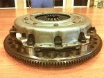
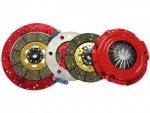
Before we get into all the speeds and feeds stuff here is a picture of the finished piece assembled,
![]()
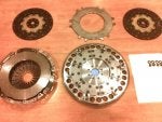
and also apart to see the components.
![]()
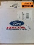
I sourced the clutch components from Ford, Crower, the local farm tractor clutch shop and the local water jet/laser cut job shop. Drive stand fasteners were sources from ARP in ARP 2000 material. The easiest item to identify and source was the pressure plate. It is a Ford unit that Ford calls their M-7563-C302N pressure plate. This particular plate is a 10.4" diameter diaphragm unit with about 40% more plate load than a stock clutch and a (reportedly) higher ratio diaphragm spring to produce a near stock pedal feel. Here is the box from Ford,
![]()
As you can see from the box, Ford is eager to let you know this unit has no warranty associated with it. What it does have though is an excellent ductile iron pressure plate, a high plate load and a (reportedly) stock feel to the clutch pedal. The price through Tousley was just over $100. I think it was $105 but don't recall exactly. Steve at Tousley can dial you in quickly price-wise.
The next item required was a flywheel. I like steel some people like aluminum. Beauty is in the eye of the beholder and also his wallet. The steel wheel was a SFI compliant wheel when I bought it - but not after I began machining on it. The price was $129. Here is what it looked like in its virgin condition,
![]()
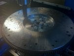
I decided I wanted to have a visual check for when I approached the finished OD for the heat shields so I didn't accidentally go too big. The mill and a rotary table allowed me to make a shadow mark where I wanted to stop cutting on the lathe. After the shadow mark the flywheel came out of the mill and went to the lathe for the heavy metal removal.
![]()
When the well for the heat shields was finished the flywheel returned back to the mill for the next operation which was the peripheral lightening holes. Checkout post #3 for more ...
Before we get into all the speeds and feeds stuff here is a picture of the finished piece assembled,
and also apart to see the components.
I sourced the clutch components from Ford, Crower, the local farm tractor clutch shop and the local water jet/laser cut job shop. Drive stand fasteners were sources from ARP in ARP 2000 material. The easiest item to identify and source was the pressure plate. It is a Ford unit that Ford calls their M-7563-C302N pressure plate. This particular plate is a 10.4" diameter diaphragm unit with about 40% more plate load than a stock clutch and a (reportedly) higher ratio diaphragm spring to produce a near stock pedal feel. Here is the box from Ford,
As you can see from the box, Ford is eager to let you know this unit has no warranty associated with it. What it does have though is an excellent ductile iron pressure plate, a high plate load and a (reportedly) stock feel to the clutch pedal. The price through Tousley was just over $100. I think it was $105 but don't recall exactly. Steve at Tousley can dial you in quickly price-wise.
The next item required was a flywheel. I like steel some people like aluminum. Beauty is in the eye of the beholder and also his wallet. The steel wheel was a SFI compliant wheel when I bought it - but not after I began machining on it. The price was $129. Here is what it looked like in its virgin condition,
I decided I wanted to have a visual check for when I approached the finished OD for the heat shields so I didn't accidentally go too big. The mill and a rotary table allowed me to make a shadow mark where I wanted to stop cutting on the lathe. After the shadow mark the flywheel came out of the mill and went to the lathe for the heavy metal removal.

When the well for the heat shields was finished the flywheel returned back to the mill for the next operation which was the peripheral lightening holes. Checkout post #3 for more ...


") . You can PM me if you want, but this does look like a nice alternative to the RXT I was considering ordering.
. You can PM me if you want, but this does look like a nice alternative to the RXT I was considering ordering.

