Thread update: Table of Contents
Since this thread has gotten long and I've received many PM's on Facebook and e-mail with questions about the build, I figured a ToC would help anyone searching. It is based on 15 posts per page, and is also broken down in groups and now with hyperlinked post numbers. In the event some quick info is needed, this should make it easy! Also, all hyperlinks, other than the obvious cut-and-paste links are bold so they stand out and are easier to recognize, especially when not logged in.
p.1 (Posts 1-15): Short block, pistons, heads, '98 Cobra cams, bearings, ARP parts list, oil pump & windage tray
p.2 (Posts 16-30): Oil cooler gasket, block heater, head gaskets, more on ARP
p.3 (Posts 31-45): Timing components, cam bolts
p.4 (Posts 46-60): Timing cover bolt modification (aluminum block), upgraded secondary tensioner
p.5 (Posts 61-75): Cam degree tools
p.6 (Posts 76-90): Misc. chat
p.7 (Posts 91-105): Oil slinger discussion
p.8 (Posts 106-120): Oil slinger cont., rear main seal
p.9 (Posts 121-135): Rear main seal cont.
p.10 (Posts 136-150): King bearing tech from Ed
p.11 (Posts 151-165): King bearing tech cont., GT-500 rockers, timing cover hole (Cont. from P.4)
p.12 (Posts 166-180): Degreeing the cams, '98 specs
p.13 (Posts 181-195): Degreeing the cams cont., timing cover, cam follower install
p.14 (Posts 196-210): Primary tensioner ratchet modification
p.15 (Posts 211-225): Primary tensioner spacer modification (update to P.14)
p.16 (Posts 226-240): Primary tensioner spacer modification cont.
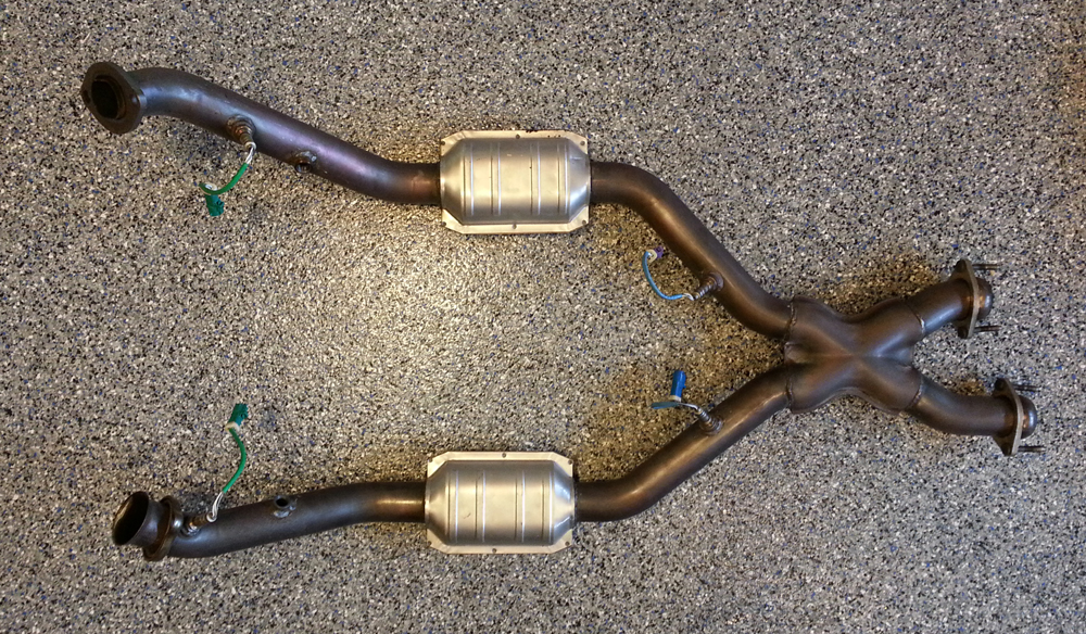
p.17 (Posts 241-255): Valve cover mock-up, exhaust manifolds
p.18 (Posts 256-270): Tensioner spacer info from Ed, ready to pull "old" engine
p.19 (Posts 271-285): Oil cooler, PCV fitting for aluminum block
p.20 (Posts 286-300): Quick Seat info
p.21 (Posts 301-315): Old vs. new piston trivia, valve covers
p.22 (Posts 316-330): New engine installed, Centerforce clutch
p.23 (Posts 331-345): Crank damper, accessory belts
p.24 (Posts 346-360): Transmission install, accessory belts cont.
p.25 (Posts 361-375): Power steering pump and A/C install notes
p.26 (Posts 376-390): First start!
p.27 (Posts 391-405): First start cont.
p.28 (Posts 406-420): Notes on PTW clearances from Ed, Vampire introduction
p.29 (Posts 421-435): Rod clearance notes from Ed, block bore information
p.30 (Posts 436-450): OE piston trivia
p.31 (Posts 451-465): Misc. oil pan discussion
p.32 (Posts 466-480): Head stud info & torque notes from Ed, wideband install, PCM harness info
p.33 (Posts 481-495): PCM connector notes
p.34 (Posts 496-510): Gauge install, oil pressure sensor, billet oil filter
p.35 (Posts 511-525): Oil and pump discussion
p.36 (Posts 526-540): Head stud re-torque
p.37 (Posts 541-555): Head stud re-torque cont.
p.38 (Posts 556-570): Head stud re-torque cont.
p.39 (Posts 571-585): Project cost sheet, Vampire install completion
p.40 (Posts 586-600): Vampire adjustments
p.41 (Posts 601-615): AFR and piston notes from Ed, Vampire gauge addition
p.42 (Posts 616-630): More from Ed on detonation, new CAI
p.43 (Posts 631-645): Vampire gauge video clip
p.44 (Posts 646-660): Dyno tune results and video clip (11/1/16), new oil separator
p.45 (Posts 661-675): Switch to Mobil1 0W-40 & UOA, piston wrist pin discussion, updated alternator
p.46 (Posts 676-690): General alternator discussion
p.47 (Posts 691-705): Bolt torque & #5 thrust bearing comments, upgraded tensioner, Whipple 2.3 on the way
p.48 (Posts 706-720): Whipple talk, new intercooler, more fuel system chat
p.49 (Posts 721-735): More on the Vampire, 4.6 vs Coyote discussion, intercooler pictures
p.50 (Posts 736-750): Eaton removed, intercooler comparison pics, Whipple installed, intercooler tech
p.51 (Posts 751-765): Some e85 talk, first drive with the Whipple and new intercooler
p.52 (Posts 766-780): Visit to Gibtec, some info on Prolong
p.53 (Posts 781-): More on Prolong, new Explorer ST to go with the Cobra.
-----------------------------------------------------------------------------------------------------------------------
This project had been in the works for a while: started a few years back when I picked up a brand new set of FRPP heads and a like-new Aluminator block for less than $2,000, which sat in storage until now. The smart thing to do would have been to sell the goods and make some money, especially since my OEM engine only has 21,000 miles on it, but who can resist tinkering. Adding to that, when you can make something leaps and bounds better, might as well enjoy the fruits of your labor while you have the chance.
I'll actually begin with a shot of where I am as of the date I decided to start this thread (fall of '15), but will go backwards to the early stages and update it little by little with as much tech as I can. Since there are not a lot of Aluminator builds out there, hopefully this will be helpful to anyone considering this route. Here's the long block:
![]()
Before moving on, I have to pass on a world of thanks to Ed for designing the finest 2618 aluminum piston out there through Gibtec of Denver, and for his willingness to help out so many on this forum with the encyclopedia of knowledge he possesses!! For those that haven't seen the Gibtec "Custom ModMotor Piston" thread, here are my specs (0.002" oversize) and pics added from it:
![Image]()
![]()
![]()
![]()
I also intended to add an Aluminator build page up on my own site, but for now it just serves as a link back here since this got long. For anyone curious about the Aluminator block, this Castings page has a bunch of information on what makes it such a great choice! Stay tuned, more to come...
Since this thread has gotten long and I've received many PM's on Facebook and e-mail with questions about the build, I figured a ToC would help anyone searching. It is based on 15 posts per page, and is also broken down in groups and now with hyperlinked post numbers. In the event some quick info is needed, this should make it easy! Also, all hyperlinks, other than the obvious cut-and-paste links are bold so they stand out and are easier to recognize, especially when not logged in.
p.1 (Posts 1-15): Short block, pistons, heads, '98 Cobra cams, bearings, ARP parts list, oil pump & windage tray
p.2 (Posts 16-30): Oil cooler gasket, block heater, head gaskets, more on ARP
p.3 (Posts 31-45): Timing components, cam bolts
p.4 (Posts 46-60): Timing cover bolt modification (aluminum block), upgraded secondary tensioner
p.5 (Posts 61-75): Cam degree tools
p.6 (Posts 76-90): Misc. chat
p.7 (Posts 91-105): Oil slinger discussion
p.8 (Posts 106-120): Oil slinger cont., rear main seal
p.9 (Posts 121-135): Rear main seal cont.
p.10 (Posts 136-150): King bearing tech from Ed
p.11 (Posts 151-165): King bearing tech cont., GT-500 rockers, timing cover hole (Cont. from P.4)
p.12 (Posts 166-180): Degreeing the cams, '98 specs
p.13 (Posts 181-195): Degreeing the cams cont., timing cover, cam follower install
p.14 (Posts 196-210): Primary tensioner ratchet modification
p.15 (Posts 211-225): Primary tensioner spacer modification (update to P.14)
p.16 (Posts 226-240): Primary tensioner spacer modification cont.
p.17 (Posts 241-255): Valve cover mock-up, exhaust manifolds
p.18 (Posts 256-270): Tensioner spacer info from Ed, ready to pull "old" engine
p.19 (Posts 271-285): Oil cooler, PCV fitting for aluminum block
p.20 (Posts 286-300): Quick Seat info
p.21 (Posts 301-315): Old vs. new piston trivia, valve covers
p.22 (Posts 316-330): New engine installed, Centerforce clutch
p.23 (Posts 331-345): Crank damper, accessory belts
p.24 (Posts 346-360): Transmission install, accessory belts cont.
p.25 (Posts 361-375): Power steering pump and A/C install notes
p.26 (Posts 376-390): First start!
p.27 (Posts 391-405): First start cont.
p.28 (Posts 406-420): Notes on PTW clearances from Ed, Vampire introduction
p.29 (Posts 421-435): Rod clearance notes from Ed, block bore information
p.30 (Posts 436-450): OE piston trivia
p.31 (Posts 451-465): Misc. oil pan discussion
p.32 (Posts 466-480): Head stud info & torque notes from Ed, wideband install, PCM harness info
p.33 (Posts 481-495): PCM connector notes
p.34 (Posts 496-510): Gauge install, oil pressure sensor, billet oil filter
p.35 (Posts 511-525): Oil and pump discussion
p.36 (Posts 526-540): Head stud re-torque
p.37 (Posts 541-555): Head stud re-torque cont.
p.38 (Posts 556-570): Head stud re-torque cont.
p.39 (Posts 571-585): Project cost sheet, Vampire install completion
p.40 (Posts 586-600): Vampire adjustments
p.41 (Posts 601-615): AFR and piston notes from Ed, Vampire gauge addition
p.42 (Posts 616-630): More from Ed on detonation, new CAI
p.43 (Posts 631-645): Vampire gauge video clip
p.44 (Posts 646-660): Dyno tune results and video clip (11/1/16), new oil separator
p.45 (Posts 661-675): Switch to Mobil1 0W-40 & UOA, piston wrist pin discussion, updated alternator
p.46 (Posts 676-690): General alternator discussion
p.47 (Posts 691-705): Bolt torque & #5 thrust bearing comments, upgraded tensioner, Whipple 2.3 on the way
p.48 (Posts 706-720): Whipple talk, new intercooler, more fuel system chat
p.49 (Posts 721-735): More on the Vampire, 4.6 vs Coyote discussion, intercooler pictures
p.50 (Posts 736-750): Eaton removed, intercooler comparison pics, Whipple installed, intercooler tech
p.51 (Posts 751-765): Some e85 talk, first drive with the Whipple and new intercooler
p.52 (Posts 766-780): Visit to Gibtec, some info on Prolong
p.53 (Posts 781-): More on Prolong, new Explorer ST to go with the Cobra.
-----------------------------------------------------------------------------------------------------------------------
This project had been in the works for a while: started a few years back when I picked up a brand new set of FRPP heads and a like-new Aluminator block for less than $2,000, which sat in storage until now. The smart thing to do would have been to sell the goods and make some money, especially since my OEM engine only has 21,000 miles on it, but who can resist tinkering. Adding to that, when you can make something leaps and bounds better, might as well enjoy the fruits of your labor while you have the chance.
I'll actually begin with a shot of where I am as of the date I decided to start this thread (fall of '15), but will go backwards to the early stages and update it little by little with as much tech as I can. Since there are not a lot of Aluminator builds out there, hopefully this will be helpful to anyone considering this route. Here's the long block:

Before moving on, I have to pass on a world of thanks to Ed for designing the finest 2618 aluminum piston out there through Gibtec of Denver, and for his willingness to help out so many on this forum with the encyclopedia of knowledge he possesses!! For those that haven't seen the Gibtec "Custom ModMotor Piston" thread, here are my specs (0.002" oversize) and pics added from it:


I also intended to add an Aluminator build page up on my own site, but for now it just serves as a link back here since this got long. For anyone curious about the Aluminator block, this Castings page has a bunch of information on what makes it such a great choice! Stay tuned, more to come...


")